Access Control System Overview
Security Access Control System
Basic Elements
and Architecture
Physical Security and Access Control Systems
have become necessary for most companies. Large or small, companies need
to protect their facilities, data, and personnel. The following provides
a cursory look at what is involved in a Physical Security and Access
Control System, elements and architecture, with a description of its components.
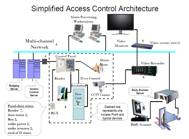
Fig. 1: General Access Control System Architecture

Why implement an Access Control System?
-Provide “Controlled Access” to the facility
-Allow access only to authorized personnel for each area
-Implement a ‘Security Protocol & Policy’ to make employees, visitors,
and the facility safe
-Implement a security and access level hierarchy based on personnel
function
-Automate and enhance the identification process
-Automate personnel tracking
-Minimize human error
-Track outside contractors and vendors
-Record and generate reports of access for each area
Automated Access Control Advantage
-Eliminate the need to man all access points
-Take full, and orderly control of your site
-Improve security measures and provide convenient access for authorized
personnel
-Improve response to emergencies
-Ability to lock down entire areas quickly at high threat levels
-Track personnel movement and access
-Establish and enforce one set of access rules
-Eliminate the “buddy” system
-Provide safety for visitors and employees
-Archive records for potential future use
The following is a brief description of components comprising an access
control system. Referring to the diagram above, each element is numbered
and briefly described. All these parts are required, in one form or
another, to secure your facility. You may not think about the process,
but when you present your card to a reader, or a biometric device, a lot
of things happen before the door opens to allow entry.
The Access Control System (ACS) Server (1) runs the software. It may contain
many servers in one machine, or distributed amongst many machines. This
server is responsible for assigning access to, and tracking traffic in
secure areas. It maintains a database of credential holders, and their
access level. It also communicates with ACS panels to download specific
data to each panel for local storage. There are various methods this server
could communicate with the ACS panels. If the panels are equipped with
Network cards, the communication could be TCP/IP based. If the panels
are equipped with RS-485 multi-drop interface, then the server, (via an
RS-232 to RS-485 converter (4)), will communicate with each panel on the
serial bus, polling each panel, and processing the panel data. The ACS
Server can also provide a “host grant” upon request from panels that do
not have the most up-to-date information. The ACS server refreshes the
panels on a scheduled basis, however, in the meantime the personnel will
be provided with host grant until such time.
The Badging Server (2) is where authorized personnel’s
data is kept. The server will process the data and issue (print)
credentials (badges). Normally, the employee, or contractor receives a
badge with numerous information encoded, including a photo, name,
address, organization, date of issue, access areas, expiration date,
restrictions, and other necessary information. If biometric readers are
employed at the site, a sample of finger print, or iris scan may be
encoded as well. The Badging Server is networked with the ACS server so
badges can be updated in the ACS Server database, and downloaded to the
access panels where the credential holders are allowed access. This
download takes place when changes are made to the access areas,
personnel, access levels, etc.
Ethernet Router or Switch (3) {self explanatory}
RS-232 to RS-485 Converter (4): RS-232 is a serial
interface with parallel control lines to control the flow of data. Not
all signals are necessary in all cases. The serial port of a computer
uses pins 2, 3, and 5. RTS line is usually looped to CTS for non-flow
control applications, and since there is no phone modem, RI and CD are
not used. RS-232 uses “single-ended” drivers, and receivers. The table
below describes the signal names and the associated pins.
|
Pin Description |
Symbol |
Pin Number |
 |
Carrier Detect |
CD |
1 |
|
|
Receive Data |
RD |
2
|
|
|
Transmit Data |
TD
|
3
|
|
| Data
Terminal Rdy |
DTR
|
4
|
|
|
Signal Ground |
SG |
5
|
|
| Data
Set Ready |
DSR |
6 |
|
|
Request to Send |
RTS |
7
|
|
|
Clear to Send |
CTS |
8 |
|
| Ring
Indicator |
RI
|
9 |
|
Table 1: 9-pin RS-232 (computer com-port) signal
description
RS-485 is a differential multi-drop bus. Only data
and ground lines connect to all devices.

Fig. 2: RS-485 Multi-drop interface with differential
drivers and receivers. Click on the link for a short overview of Serial Multidrop Bus Protocol.
The video router/switch (5) provides the capability of
observing any camera, or a multiplexed view in the system client
workstation.
The digital video recorder (6) is usually on, recording
the events on a loop basis. The duration of the loop is based on the
customer requirements. There are many cameras in a large enterprise
system, and there maybe many recorders as well. Recorders are usually
assigned to a limited number of cameras based on their storage capacity,
but none-the-less, are necessary to exist on the same IP network so
events can be recalled, and replayed on-demand, per area.
The control Panels (7) provide the gateway between the
control points (door, checkpoint) and the ACS server. On the door side,
they process the reader data, report the door position (open, closed),
accept a request to exit from the secure side, and order the electric
door strike to open, or remain closed. On the server side, they respond
to polls, report intrusion, alarms, credential problems, tamper alarms,
and a number of other information as required to make the area safe.
Panels hold user credential data on local memory in case the
communication between the panel and the server is unavailable. Panels
will operate on stand-alone until the communication is restored. There
are many flavors of panels, and interfaces connecting the panel to the
server. Some panels communicate with the server on Ethernet protocol,
some on RS-485 multi-drop bus. On the check-point side, however, the
signals are fairly standard. The garden variety panels normally control
2 check-points (doors), but there are panels with expansion slots that
can extend to several doors. A typical panel-door connection is shown
below (Honeywell® NS2+):
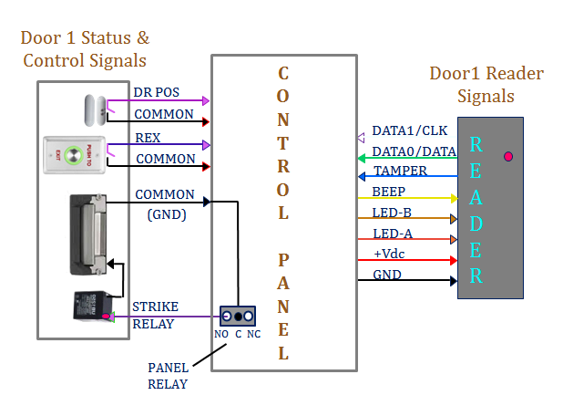
Fig 3: Typical wiring from the Control Panel to the
door hardware
Door Hardware (8) is composed of a reader, door
position switch, request to exit button, and an electric door strike.
There are many varieties of readers, with different technologies.
Wiegand format data (data0, data1), Magnetic stripe format (data,
clock), and biometric decoders (finger print readers, Iris scanners).
The readers employ a wire winding to produce a magnetic field. When a
card is presented to the reader, the magnetic field produces an electric
field in the card winding, supplies power to the processor in the card, and the
data packet containing the user information is transferred from the card
to the reader. The reader transmits the data to the control panel, which
actuates a relay to apply power to the door strike to open (if the user
has access), or report an invalid card (if the user does not have access
to the area). There are many card formats used in the industry ranging
from 26-bit to FIPS-201 compliant formats with FASC-N length of 200
bits. Many organizations exceed the 200-bit card format, extending to
512, or 1024 bits.
Reader examples: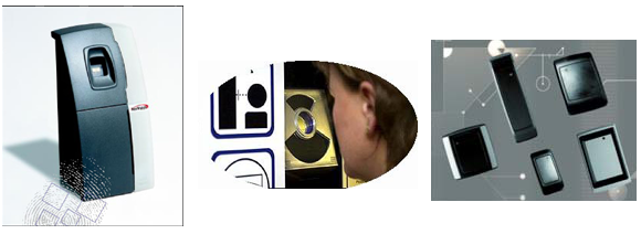
 Door
position switch is usually a magnetic switch. While both parts
of the switch are in proximity of each other, the switch is closed,
otherwise open.
Door
position switch is usually a magnetic switch. While both parts
of the switch are in proximity of each other, the switch is closed,
otherwise open.
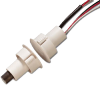
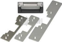 Electric strike is a solenoid actuated device that releases the lock so
the door can be pushed without turning the door knob or handle. The
input power is 12, or 24 Vdc. In some cases, magnetic locks are employed
so when energized, the door is magnetically held by the door frame part
of the lock.
Electric strike is a solenoid actuated device that releases the lock so
the door can be pushed without turning the door knob or handle. The
input power is 12, or 24 Vdc. In some cases, magnetic locks are employed
so when energized, the door is magnetically held by the door frame part
of the lock.
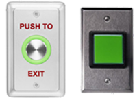 Request
to exit / Egress is a momentary closure switch that is normally
de-bounced. When pressed, the circuit closes and signals the panel to
release the door lock, allowing graceful exit from a secure area.
Request
to exit / Egress is a momentary closure switch that is normally
de-bounced. When pressed, the circuit closes and signals the panel to
release the door lock, allowing graceful exit from a secure area.
Wireless Access Control System eliminates wiring,
trenching, conduit installation, core drilling, asbestos abatement, and
variety of problems associated with installation. The connection between
the ACS server and panels can be done wirelessly using
WILDR-MIU. Also, the
connection between any panel and a checkpoint or a door can be
implemented by WILDR-MIU1.
All panel to door connections are handled by WILDR-MIU1. WILDR-MIU1 also supplies
power to the door strike and the reader eliminating the requirement for
an extra battery. Please visit the
services tab, wireless, for detail information.
Watch WILDR Data Center Demo