Broadband Networks
Network Implementation Process;
Design, Installation, and Certification
Broadband Network Alignment and Certification is admittedly the
most fun part of an RF broadband LAN implementation project.
 The
design is always based on component's worst case performance! Of course,
the components will typically perform at their nominal parameters. The
job of the field alignment and certification engineer is to perform
network alignment based on amplifier, or fiber node I/O parameters to achieve
the correct output at the customer tap. Selecting proper equalizers, pads (plug-in
or in-line), adjusting the amplifier gain, and output spectrum slope is
the key to success. Keep in mind that the amplifier output level must
conform to manufacturer specs to maintain the distortion specifications.
The
design is always based on component's worst case performance! Of course,
the components will typically perform at their nominal parameters. The
job of the field alignment and certification engineer is to perform
network alignment based on amplifier, or fiber node I/O parameters to achieve
the correct output at the customer tap. Selecting proper equalizers, pads (plug-in
or in-line), adjusting the amplifier gain, and output spectrum slope is
the key to success. Keep in mind that the amplifier output level must
conform to manufacturer specs to maintain the distortion specifications.
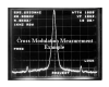
Once the system is spectrally
aligned, the network is loaded with carriers, and distortion tests are
conducted. Carrier-to-noise, composite triple beat, second order
distortion, and cross-modulation tests define the system performance. It
is not sufficient to deliver the correct RF level to the tap output, it
must also conform to the proper distortion values. Balancing the
distortion performance, and the RF output levels is the art of system
alignment, and certification.
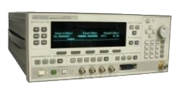
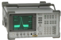 Of
course, proper instruments are an essential part of certification.
Generally, RF system certifiers use Field Strength Meters, and test just
a few channels. Our engineers use Spectrum analyzers on a loaded system
to observe the complete band, and if need be, focus on individual channels
to further investigate any abnormality.
Of
course, proper instruments are an essential part of certification.
Generally, RF system certifiers use Field Strength Meters, and test just
a few channels. Our engineers use Spectrum analyzers on a loaded system
to observe the complete band, and if need be, focus on individual channels
to further investigate any abnormality.
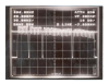
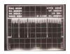
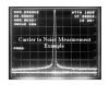
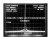
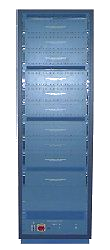
Example photos of certification
are shown below. Amplifier I/O, Carrier-to-Noise, Composite Triple Beat,
and Cross-Modulation.